High-capacity electrical distribution needs more than a suitable current rating. Loads can change during production, new equipment may be connected, and operating temperatures can vary with the installation environment. These changes can place extra thermal stress on conductors and connection points.
Overload protection is used to limit the effects of excessive current before heat causes damage to electrical components. For engineers and project teams, understanding the relationship between load calculation, conductor capacity, protective devices, and heat dissipation makes equipment selection more practical.
Why Does an Electrical Overload Happen?
An electrical overload occurs when a circuit carries current above its intended operating capacity for a period of time. This situation is different from a short circuit. A short circuit creates a fault path with very low impedance and can produce a rapid increase in current.
Industrial overloads can develop in several ways. A factory may add motors or production equipment without changing the original distribution design. HVAC systems, welding equipment, electric heating loads, and charging equipment can also raise the total operating current.
Phase imbalance deserves attention in three-phase installations. If one phase carries a much higher current than the others, heat may not be distributed evenly. Load calculations should therefore examine phase currents rather than only the total connected load.
Busbar Trunking Systems and Rated Current
Rated current is one of the first specifications engineers check when selecting a distribution system. However, the rated current should be considered together with conductor material, cross-sectional area, ambient temperature, enclosure design, and installation conditions.
Busbar trunking uses enclosed conductors to distribute electrical power along a defined route. Compared with long runs of individual cables, a modular busbar arrangement can provide designated connection points for equipment. This can be useful when industrial layouts contain multiple loads along the same distribution path.
Selection should start with the expected operating current. Engineers can then compare that value with the rated current of the selected system and review the manufacturer’s technical data. Future load growth should also be considered when the project has planned production expansion.
How Do Protective Devices Respond?
Circuit breakers are commonly used to protect electrical distribution circuits. Thermal protection responds to sustained overcurrent by detecting the heating effect of excessive current. Magnetic protection responds much faster to high fault currents.
Breaker selection should match the circuit rating and connected load. Trip characteristics also matter. Motors, transformers, and other equipment can produce temporary current changes during startup, so protection settings should account for the normal operating characteristics of the connected equipment.
Coordination between upstream and downstream protection is another important design point. A local fault or overload should be isolated as close to the affected circuit as practical. Poor coordination can cause a larger section of a facility to lose power when a smaller circuit has a problem.
Heat Is a Key Part of Overload Protection
Electrical current produces heat as it passes through a conductor. Resistance, current level, and operating time all influence the amount of heat generated. Higher ambient temperatures can further affect the thermal condition of an electrical installation.
Connection points require particular attention. A loose joint can increase contact resistance and create localized heating. Similar concerns can occur at tap-off units, cable terminations, and other connection areas. Regular inspection can identify discoloration, unusual temperature rise, or changes in connection condition.
Installation conditions also influence heat dissipation. Restricted ventilation, nearby heat sources, and insufficient clearance can change the thermal environment. Project teams should therefore follow the installation requirements provided for the selected electrical equipment.
Where Does Busbar Design Fit Into Protection?
Overload protection depends on both correctly selected protective devices and suitable electrical and mechanical characteristics of the distribution equipment. Compact construction, stable connections, and effective heat dissipation can influence how a system performs under normal operating loads.
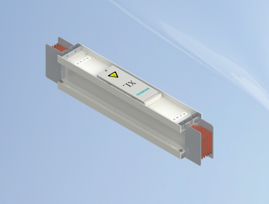
Daqo Group offers the XL-III Sandwich Busbar Trunking System for high-capacity three-phase AC power transmission and distribution. The series is used in automotive manufacturing, industrial plants, metallurgical facilities, and high-rise buildings.
The XL-III series uses a sandwich structure designed for efficient heat dissipation. Its stated characteristics include low impedance and low power loss. The system has a service life of over 30 years and is certified by CCC, KEMA, and ASTA. It complies with IEC 61439 and GB/T 7251, with seismic resistance up to intensity 9.
What Should Engineers Check Before Energizing the System?
Commissioning provides an opportunity to compare the planned design with the installed system. Engineers can verify breaker ratings, protection settings, phase connections, busbar joints, and tap-off units before the system enters regular operation.
Load measurements can also provide useful information. Current should be checked across the three phases where applicable. Unexpected differences may indicate an uneven load arrangement that needs further review.
Physical inspection is equally important. Connection points should be assembled according to the specified requirements. Protective conductors and grounding connections should also be checked. Clear documentation of breaker settings and equipment ratings can make later maintenance easier.
Planning for Future Load Changes
Industrial electrical demand rarely stays fixed throughout the life of a facility. Production lines may be expanded, equipment may be replaced, or additional loads may be introduced. These changes can affect the original distribution calculations.
Modular distribution equipment can be useful when a project requires staged expansion. Engineers can plan the main routes and connection points around expected future loads instead of treating every modification as a separate installation.
For large projects, the protection strategy should therefore consider both present and planned demand. Rated current, breaker settings, thermal conditions, connection quality, and installation layout should be reviewed together. Daqo Group provides integrated low- and medium-voltage distribution products, which can give project teams more options when coordinating equipment for different applications.
Making Overload Protection Practical
A reliable protection strategy begins with accurate load information. Engineers need to know the expected operating current, equipment characteristics, installation environment, and possible changes in demand. Protective devices can then be selected according to the actual circuit conditions.
The same principle applies when choosing busbar trunking systems. Current rating should be reviewed alongside thermal performance, connection design, installation requirements, and future expansion plans. Treating these factors as one design task makes overload protection easier to evaluate.
For industrial and infrastructure projects, practical protection is not based on a single breaker or rating. Load calculation, thermal design, coordinated protection, secure connections, and suitable distribution equipment all have a role. A clear review of these elements can help project teams build a power distribution system suited to long-term operating needs.
